
3D printed metal parts are tested at several stages before they reach customers: the metal powder is checked before printing, the build is monitored layer by layer, finished parts are inspected for internal defects with methods such as X-ray computed tomography, and mechanical properties are confirmed through tensile, hardness and sometimes fatigue testing. Dimensional checks and surface measurements complete the picture before a part is released.
The reason for this layered approach is that additive manufacturing creates the material and the part at the same time. In conventional manufacturing, a supplier certifies a bar or plate, and the machinist shapes it. In a printed part, the metal’s microstructure, density and strength are all formed during the build, so every stage of the process can affect the final properties.
Why Metal Additive Parts Need More Testing Than Conventional Parts
In powder bed fusion, the most common metal printing process, a laser or electron beam melts thin layers of powder, typically 20 to 60 micrometres thick, one after another. Each layer cools and reheats many times as the layers above it are melted. That thermal history creates microstructures that differ from wrought or cast material, and properties can vary with build direction, location on the build plate and part geometry.
Defects also behave differently. Lack-of-fusion voids, trapped gas porosity and unmelted particles can appear inside a part that looks perfect from the outside. Well-tuned processes routinely reach densities above 99.5 percent, but a small cluster of defects in the wrong place can still reduce fatigue life significantly. This is why aerospace, medical and energy customers usually require evidence that each build meets specification, not just that the process works in principle.
Checking the Powder and Monitoring the Build
Testing starts before printing. Powder is checked for particle size distribution, shape, flowability and chemistry, including oxygen and nitrogen content, which can rise each time powder is reused. Many manufacturers track how many times a batch has been recycled and set limits on reuse, since degraded powder can lead to porosity and reduced ductility.
During the build, in-process monitoring has become increasingly common. Cameras capture images of each layer to spot recoating problems or distortion, and sensors monitor the melt pool for irregular behaviour that might indicate a defect forming. These systems don’t replace final inspection, but they help flag builds or regions that need closer attention and provide a record of how each part was made.
Most production builds also include witness coupons, small test specimens printed alongside the parts on the same plate. These are later machined into tensile bars, sectioned for microstructural analysis or tested for density, giving a sample of the material produced in that specific build.
Finding Hidden Defects With Non-Destructive Inspection
After printing, parts usually go through heat treatment to relieve residual stresses, and critical components are often put through hot isostatic pressing, which applies high temperature and pressure to close internal pores. Then comes non-destructive inspection to confirm that no significant defects remain.
X-ray computed tomography is the most powerful tool here. It produces a three-dimensional image of the part’s interior, revealing porosity, lack-of-fusion defects and trapped powder in internal channels, while also allowing internal dimensions to be checked against the design. The drawback is cost and time, with scans often running into hundreds of pounds per part, so it’s typically used for critical components, first articles or a statistical sample of production.
Surface methods such as dye penetrant testing detect cracks that break the surface, and ultrasonic testing can work on simpler geometries. Dimensional inspection using coordinate measuring machines or 3D scanning confirms that the part matches its design, and surface roughness is measured where it matters, as printed surfaces are rougher than machined ones and can influence fatigue performance.
Confirming Mechanical Properties Across the Build
Mechanical testing is where many manufacturers face their biggest bottleneck. Tensile tests on witness coupons are the standard way to confirm yield strength, ultimate tensile strength and elongation, and specifications often require specimens printed in different orientations, as vertical and horizontal specimens can show different properties. Machining, testing and reporting can add days or weeks before parts are released.
Witness coupons also have a known limitation. They’re printed nearby but not inside the part, and their thermal history can differ from that of a thick section or a thin wall in the actual component. Engineers increasingly want to know the properties of specific regions of the part itself, not just of a separate specimen that shares the same build plate.
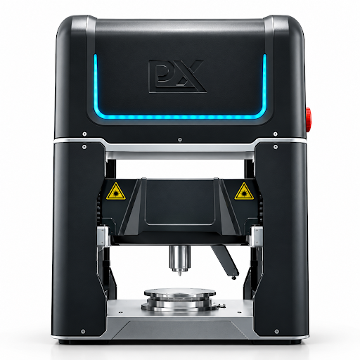
This is where indentation plastometry has found a role in additive manufacturing. By measuring the shape of a small spherical indent and using modelling to derive the stress-strain curve, the technique provides tensile-type properties from a very small test area. With a benchtop plastometer, a quality lab can test small coupons, offcuts or sections of the part itself in minutes, which makes it practical to compare properties across different build locations, orientations and heat treatments without machining a full set of tensile bars each time.
Hardness testing is still widely used for quick checks of heat treatment consistency, and fatigue testing is essential for parts that experience cyclic loading, such as aerospace brackets and orthopaedic implants. Fatigue tests are slow and expensive, so they’re usually part of process qualification rather than routine release testing.
How Testing Requirements Differ Between Industries
Aerospace customers typically demand the most extensive testing. Processes are qualified in detail, parameters are locked once approved, and every production build is accompanied by witness coupon results, inspection records and full traceability back to the powder batch. Critical parts may undergo CT scanning individually.
Medical implants face similarly strict requirements, with additional attention to surface condition, cleanliness and biocompatibility. Porous structures designed to encourage bone growth need their own checks to confirm that pore size and connectivity match the design.
In automotive, motorsport and industrial tooling, the balance often shifts towards speed and cost. Testing may focus on process qualification and periodic sampling rather than inspecting every part in depth, particularly for components that aren’t safety-critical. Energy sector parts, such as turbine components or valve parts, sit somewhere in between, with requirements driven by operating temperatures and pressures.
For anyone setting up or buying from a metal additive manufacturing operation, the most useful question is how quickly and how representatively mechanical properties can be verified. Powder checks and CT scans are well established, but the time between printing a part and confirming its strength often decides how fast production can move. Building a testing plan that measures properties close to the actual part, and returns results in hours rather than weeks, is increasingly what separates a prototype workshop from a reliable production supplier.