
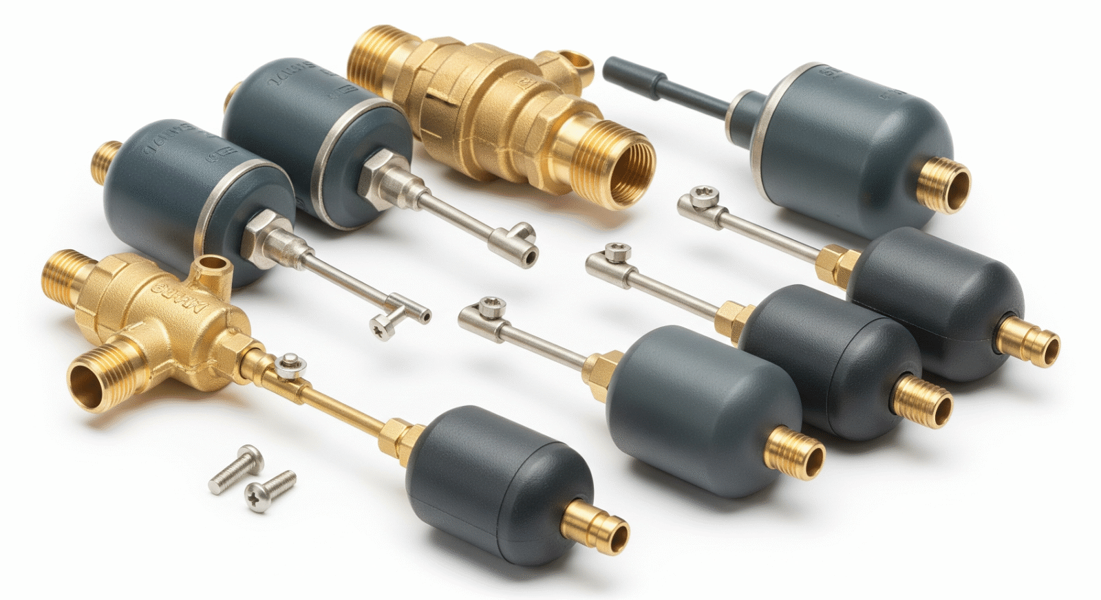
When a fluid system fails to maintain consistent levels, the consequences tend to compound quickly. Tanks overflow or run dry, downstream processes lose feed consistency, and maintenance teams spend time diagnosing problems that were never clearly documented in the original equipment specifications. In many of these situations, the root cause traces back not to a catastrophic failure but to a float controlled valve that was either selected without enough operational context or installed without accounting for the conditions it would actually face.
Specification sheets describe what a valve is. They rarely explain how it behaves under variable inlet pressure, fluctuating fluid density, or the kind of long-cycle demand patterns common in agricultural, industrial, and commercial water management. That gap between stated specifications and real-world performance is where most operational problems originate — and where a more complete understanding of how these valves actually function becomes genuinely useful.
What Float Controlled Valves Actually Do and Why the Basics Matter More Than You Think
A float controlled valve is a mechanical device that automatically regulates fluid flow into a tank or reservoir based on the position of a float connected to the valve body. As fluid rises, the float rises with it, gradually restricting flow until the valve closes at a predetermined level. When fluid drops — through consumption, drainage, or process demand — the float descends, reopening the valve and allowing fluid to re-enter. The mechanism requires no electrical input, no control signal, and no external power source. It is self-contained and self-regulating by design.
For engineers, facilities managers, and procurement professionals making selection decisions, it helps to consult a reliable Float Controlled Valve guide that goes beyond catalog descriptions and addresses how valve geometry, float material, and connection configuration interact under actual working conditions. The specification sheet tells you the pressure rating and thread size. It does not tell you how the valve responds when inlet pressure fluctuates significantly throughout the day, or how quickly it closes when demand drops suddenly.
Understanding this distinction matters because the valve’s fundamental job is not simply to open and close — it is to maintain a consistent fluid level within a defined range over time, repeatedly, without requiring human intervention. Every design decision in a float controlled valve should be evaluated against that functional requirement.
The Relationship Between Float Size, Buoyancy, and Valve Closure Force
The float itself is the sensing element of the system. Its size and material determine how much buoyant force it generates at any given fluid level, and that force is what pushes against the valve seat to restrict or stop flow. A float that is too small relative to the inlet pressure it must overcome will fail to close completely, resulting in continuous seepage and rising fluid levels. A float that is oversized may generate enough force to close the valve prematurely, creating a constant pattern of short-cycling that accelerates wear on the seat and seal components.
This relationship between float geometry and closing force is rarely stated explicitly in product documentation. The assumption is that buyers will select the correct float for the pressure range indicated. In practice, systems rarely operate at a single, stable pressure throughout the day, which means the valve must perform acceptably across a range of inlet pressures — not just at the rated maximum.
Why Material Selection Goes Beyond Corrosion Resistance
The instinct to select stainless steel components for corrosion resistance is sound, but material selection in float controlled valves carries additional implications that are often overlooked. The float material affects buoyancy consistency over time. A float that absorbs fluid — whether through microscopic porosity or seal degradation — gradually loses effective buoyancy, shifting the equilibrium point of the valve and causing it to maintain higher fluid levels than intended.
The valve body material affects thermal expansion behavior, which becomes relevant in outdoor installations subject to temperature variation. Mismatched thermal expansion between the valve seat and body can introduce small but persistent gaps at operating temperature, leading to dripping that is difficult to identify because it only occurs within a specific temperature range. Selecting materials with compatible expansion characteristics is a step that specification sheets rarely prompt buyers to consider.
Pressure Dynamics That Affect Long-Term Valve Performance
Most float controlled valve failures in long-running industrial or agricultural installations are not sudden. They develop gradually as the valve is subjected to conditions that differ in important ways from the static test conditions used during product evaluation. Pressure dynamics are the most common source of this divergence.
Inlet pressure in real systems is rarely constant. Municipal water supplies experience morning and evening demand peaks that reduce available pressure. Agricultural irrigation systems feeding from elevated storage tanks deliver pressure that decreases as the tank empties. Process water systems tied to variable-speed pumps experience pressure that changes with pump load and pipeline configuration. A float controlled valve selected for a nominal pressure rating may perform well under those rated conditions and poorly under the actual variable pressures it encounters in service.
Water Hammer and Its Effect on Float Valve Components
When a float controlled valve closes quickly against high-pressure flow, the sudden arrest of fluid movement creates a pressure wave that travels back through the supply line. This phenomenon, commonly referred to as water hammer, is well-documented in hydraulic engineering literature and recognized as a significant cause of pipe joint failure and valve component fatigue. The pressure spike generated by water hammer can exceed the static operating pressure by a considerable margin, stressing seat materials and float connections in ways that are not captured by standard pressure ratings.
Float controlled valves that close in a single stage — moving from fully open to fully closed without an intermediate slow-close phase — are more likely to generate water hammer in high-pressure systems. Valves designed with a graduated closure mechanism, where flow restriction increases progressively as the float approaches its upper limit, reduce this risk by allowing fluid velocity to decrease before the seat fully closes. This design consideration does not appear in most standard product specifications, but it has a meaningful effect on long-term system reliability and the integrity of connected pipework.
The Effect of Inlet Velocity on Float Stability
High inlet velocity creates turbulence in the tank or reservoir immediately around the valve outlet. That turbulence affects the fluid surface near the float, causing it to bob rather than rise steadily. The result is a float that signals inconsistent levels to the valve mechanism, producing rapid opening and closing cycles that generate noise, accelerate seat wear, and interfere with accurate level control. This effect is amplified in smaller tanks where the ratio of inlet velocity to tank volume is high.
Positioning the valve inlet below the operating fluid level, where possible, reduces surface turbulence by directing incoming fluid downward rather than across the surface. This is a straightforward installation adjustment that can significantly improve valve stability in systems prone to hunting — the oscillating open-close behavior caused by float instability.
Installation Context That Specification Sheets Overlook
Float controlled valve performance is not determined by the valve alone. It is determined by the combination of the valve, the tank geometry, the supply line configuration, and the operating patterns of the wider system. Specification sheets describe the valve in isolation. Real-world performance depends on all of these factors together.
Tank geometry affects how fluid level changes in response to valve flow rate. A narrow, tall tank experiences rapid level changes for a given volume of inflow or outflow, which means the float must travel a shorter vertical distance to open or close the valve fully. A wide, shallow tank requires the float to travel across a broader surface area before the same level change occurs. Valve sensitivity — the rate of closure per unit of float travel — should be matched to tank geometry, not just to flow rate.
Supply Line Length and Pressure Drop Considerations
Long supply lines between the pressure source and the valve introduce pressure drop that reduces the effective inlet pressure at the valve. This is particularly relevant in agricultural and rural installations where the distance between a pump, storage tank, or water main and the receiving tank may be substantial. A valve selected on the basis of source pressure rather than delivered pressure will be operating below its intended inlet pressure range, which affects closure force and may compromise the valve’s ability to seal completely under low-demand conditions.
The relationship between pipe diameter, flow velocity, and pressure drop is straightforward in principle but often underestimated in practice, particularly when supply lines include multiple bends, fittings, or elevation changes. Accounting for these factors at the selection stage prevents performance problems that are later attributed incorrectly to valve quality.
Maintenance Patterns That Extend or Shorten Valve Service Life
Float controlled valves are often described as low-maintenance, which is accurate relative to electrically actuated alternatives. They do not require calibration, control signals, or power supply management. However, low maintenance does not mean no maintenance, and the absence of routine inspection is a common reason that valves fail in ways that cause operational disruption rather than orderly replacement.
The seat and seal assembly is the most wear-prone component in any float controlled valve. Sediment in the supply water gradually erodes the seat surface, and mineral deposits from hard water can build up on the seal face, preventing full closure. Neither of these processes is immediately visible or audible in the early stages. Regular inspection — particularly in systems with known sediment or mineral content — allows seat wear to be identified and corrected before it results in uncontrolled flow or tank overfill events.
Float Integrity Checks in Long-Running Installations
In installations that run continuously for months or years without intervention, the float itself is a component worth examining periodically. Seam integrity in hollow metal or plastic floats can degrade over time, particularly in systems where the fluid contains cleaning agents, agricultural chemicals, or elevated mineral content. A compromised float that has taken on fluid will ride lower in the tank than its design position, causing the valve to maintain a lower operating level than intended. In storage and feed systems where consistent volume is operationally important, this shift can introduce downstream inconsistencies that are difficult to trace without inspecting the valve assembly directly.
Closing Thoughts: What Sound Selection and Installation Actually Require
Float controlled valves occupy a position in fluid management systems that is easy to underestimate. They are mechanical, passive, and relatively simple compared to electronically actuated alternatives. That simplicity is a genuine advantage — but it does not mean selection and installation decisions require less attention. It means the consequences of poor decisions are often slower to appear and harder to diagnose once they do.
A float controlled valve chosen without accounting for variable inlet pressure, tank geometry, or supply line conditions may perform acceptably for months before the accumulated effects of seat wear, water hammer stress, or float degradation produce a visible problem. By that point, the connection between the original selection decision and the current operational issue is rarely obvious.
The most reliable installations are those where the operating environment was defined before the valve was specified — where pressure variation, fluid characteristics, tank dimensions, and maintenance intervals were considered as part of the selection process rather than discovered after installation. Specification sheets provide the starting point for that process. They are not a substitute for it. Understanding what those documents do not capture is what separates installations that remain stable for years from those that require repeated attention without any clear cause.